
As some of you know, I have done a lot of work with the Si5351 series of synthesizers. In a couple of blog post, I will try to document some of the more subtile details of operation of this chip. Since I don’t have access to the actual mask sets for the chips some of these statements are qualified guessing, based on observations by NT7S and myself.
I believe the routing in the chip to be more complicated than outlined in the datasheet. Trying to determine where the spurious responses come from, and why they have their amplitudes have shown some of the internals that I will try to outline. Lets start with the block diagram, shamelessly stolen from SiLabs:
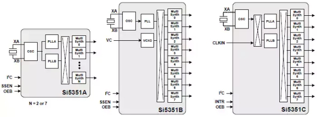
The Synthesizer consists of a crystal oscillator (or TCXO/OCXO) with drivers. The performance of this is depending on the signal quality. A good designed crystal oscillator with a limiter will outperform the internal oscillator on phase noise. Notice that the C version has a switching matrix after the oscillator and the option to feed in an external clock. This is a nice option for those cheap OCXO’s that are on non-integer frequencies.
A bit interesting is it that the datasheet mentions 25MHz and 27MHz as the alternative frequencies, but the chip works on a broad range. That 26MHz crystal will work just fine. I do believe the input frequency are divided down to 5MHz, before being distributed internally. This would then be routed out to PLL A and B, microcontroller (for the I2C) and probably to the multisynth stages as a clock.
There are both internal and external capacitors to the device. A interesting point is that when using regular crystals the spurious products seems to be reduced when selecting the internal capacitors, unlike loading with external capacitors.

The above picture is taken with PLL A set to 870MHz and the multisynth set to 6. There is up to 10dB difference between the 0pF (blue plot) and 10pF (red plot), using the internal capacitors. Selecting the 0pF internal capacitor, and using external 18pF, lead to a 10dB increase in spurs above what can be seen above. I should point out that while there are some spurs, they are not a deal breaker in this case, the above spurs can easily be removed by bandpass filtering if necessary.
The PLL’s seems to be a fairly common design, with a PLL bandwidth of around 200KHz (there are some subtile spurs). The PLL operates over the range 600MHz-900MHz. This part is the well-behaved part of the chip.
The “Multisynth” is the unknown part of the chip. I believe this is some kind of fractional divider, clocked by the PLL signal and the 5MHz internal clock. The output spurs are reduced when the divider is operated at integer divisions instead of fractional divisions. Some experiments suggest that the multisynth is followed by a divide-by-2, as the output always have a 50% duty cycle square wave.
The way to get the best performance is to lock the Multisynth at a suitable integer level, and move the PLL to do the frequency change. The output should be used with a switching type mixer (DBM with diodes in saturation or switches) in order to get the best preformance. A good limiter could reduce the spurious responses, perhaps reducing the voltage to the output buffer would help in driving them deeper into saturation, and giving better limiting action?
ADDITION 31. dec 16: The above plot is the worst case I have been able to make by abusing the Si5351. This is not at all typical performance. The 200KHz spurs is usually found at an amplitude less than -110dBc, and other spurious products should be below -70dBc. In my opinion, the chip is well suited as local oscillator in a receiver.

Hi, Nice plots, & good info, but I think this guess is not quite right, close tho :
” I do believe the input frequency are divided down to 5MHz, before being distributed internally ”
Reasoning :
When I configure for 25MHz to 145MHz, it reports
Fvco = 870 MHz
M = 34.8 [ 34 + 4/5 ]
Fout = 145 MHz
N = 6
The M is a fraction, which means mostly it divides by 35, but every 5 times, it divides by 34
In the time domain, this is 5/(4*35/870M+1*34/870M) = 25000000
That means there is a 5MHz rate inside the device, (which you see), but it is set by that M fraction, rather than fixed. The PFD will have a moving sawtooth error, that repeats at 5MHz, so there is both 5MHz activity, plus a (very small) 5MHz ripple on the VCO control voltage, the remnant after the PFD filter/integrator.
Change the M fraction, and I predict the 5MHz spurs will move.